You are using an out of date browser. It may not display this or other websites correctly.
You should upgrade or use an alternative browser.
You should upgrade or use an alternative browser.
Living with Code 25/26
- Thread starter rdmnt2002
- Start date
08 ECUs on these and some other models eg CBR1000 can be accessed for reflash via the K line, this is due to changing the main processor from OKI to MATSUSHITO, I have found rom/bin files from ST1300s post 2008 so this has been carried out more by the ECU hacking community than tune shops. The OKI was designed with whats called a "masked rom" which needed to be read on the bench. older pre 08 ECU Bench work is normally limited to key/immobiler programming which is a separate ic on board.
"S" stands for shield these 2 shield connections need to be cut from the PG1 power ground wire, this may be enough to fix the issue,
Are the shields (of the knock sensors cables) connected to ground at the other end (not apparent on schematic)?
if not connect both shields to a good earth point on engine away from any interference eg alternator
Any suggestion of alternate ground point for the (cutted) shields? As stated, multiple ground points will pick up interference currents via frame (unless chosen away from high power devices, eg alternator
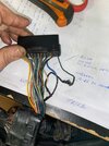
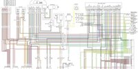
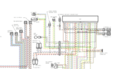
here is a connector pic from a different model so ignore exact pinouts on plug but wire color are the same, (pan european model uses this type of 26 pin connector) , following the ZOMBIE fix find, i would remove/cut green LOGIC GROUND wire and run it to a good ground on engine, the other end of the shield DOESNT GO TO GROUND and stops about 2 inches short of end of knocksensor connector. This is a bit different from the GL1800 wiring . Diagram below is ST1300 post 07, HONDA has changed the shield ground attempting to help this problem like they did in the GL1800 in 06.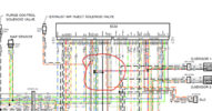
03 to 07 below:


03 to 07 below:

Attachments
- Joined
- May 27, 2021
- Messages
- 1,159
- Age
- 64
- Location
- Coquitlam British Columbia Canada
- Bike
- 2009 ST1300
I think there were some discussions on one of the sites about relocating the knock sensor ground; if I recall some system go frame to negative and some go motor to frame [to negative], and some systems gang with other grounds possibly getting some interference. The shields are also mentioned in some where changing the shield connection has been tried.
I went over pretty good [which probably means I should do it again] the wiring and connections on my blackbird with the sickness, I also installed a foam bed under the ECU to no success. I did seem also to raise some eyebrows on that site because of the low milage [4,300]. As I think you mention, there's very little change in performance with the BB when the code sets; I've never caught it occur, only noticed it for looking at the cluster for other reasons.
Many on the STs, see a set of the fault at 4,000. Some on the BB see a set at 5,000. I've tried to set it on the center stand up to 10,000 rpm, and under load through 7,000 it has not set.
I've had at least one event where it set well below 3,500 rpm. When it is set, I think it might run a bit richer, and have a little less torque in the 6,500 plus, but I dunno.
. Diagram below is ST1300 post 07, HONDA has changed the shield ground attempting to help this problem like they did in the GL1800 in 06.
Very useful info. Thanks!
please read Dannos post on knock sensing, if images do not load "right click open image in new tab"
https://www.st-owners.com/forums/threads/ecm-hope.185697/page-3
https://www.st-owners.com/forums/threads/ecm-hope.185697/page-3
Very familiar with it. Thanks for the tip on the images....thought they were forever gone!please read Dannos post on knock sensing, if images do not load "right click open image in new tab"
https://www.st-owners.com/forums/threads/ecm-hope.185697/page-3
Just to clear up some confusion regarding removing the green/logic ground from connector. I do not believe this disables knock sensing function, rather it cleans up/alters signal from knock sensor allowing knock module inside ECU to function properly again, This may only be a temporary fix, as knock module will over time drift/change and code may reappear.
In a nutshell: The module is a type of OP AMP, called a frequency multiplier that looks at a certain frequency and amplitude of signal. In this case it is around 7 KHZ, it then changes this output to a digital frequency and ampltitude that the processor can now recognise and apply the tune program algorithm to determine timing retard.
Communicating with Dark Sun he commented to me, the module gets very hot to touch when ECU is powered, the rest of ECU has no apparent warm components. This OP AMP has to process very precise and small anolog signals < 1 volt, (more like a FM radio signal) so uses laser cut resistors in the detecting circuit which are the most accurate. Whether the OP AMP begins to fail from the heat, or the resistors drift, this is the failure process. I just dont know if its the chicken or the egg that comes first. Either way the module is a POS and should never of been used...............
Last edited:
- Joined
- May 27, 2021
- Messages
- 1,159
- Age
- 64
- Location
- Coquitlam British Columbia Canada
- Bike
- 2009 ST1300
I wonder if it would be worth fitting a cold pack around the ECU and seeing if that prevents the code from setting.
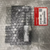
If I'm not mistaken, that's an ABS module, not an engine module.just checking on ECU models and part numbers, is this this pre or post 08 ? MCS-G01View attachment 339355
Andrew Shadow
Site Supporter
That is not an ECM, it is an ABS module.
If there have been no P/N changes the North American ECM P/N for 07 and earlier is 38770-MCS-L01. P/N for 08 and later is 38770-MCS-R12.
If there have been no P/N changes the North American ECM P/N for 07 and earlier is 38770-MCS-L01. P/N for 08 and later is 38770-MCS-R12.
Last edited:
38770-MCS-G02 Honda Unit Assy Pgm-Fi/ - KFM-Motorraeder
Honda 38770-MCS-G02 / 38770MCSG02 / 38770mcsg02 OEM Genuine Honda spare part Unit Assy Pgm-Fi/ new.
sorry missed that the first part of the number isnt 38770, gotto be the biggest ABS module for a motorbike I have ever seenjust checking on ECU models and part numbers, is this this pre or post 08 ? MCS-G01View attachment 339355
Last edited:
then this must be 08 and onwards, 33 pin connectors. This is what Crusty is fitting to his older model with an adapter loom, i still think this would be the best long term solution for these ECUs are cheaper 2nd hand $600 and have better availability. If Crustys mod works, re pinning the 33 pin connectors would be an easier solution, the 26 pin male connector is unavailable to make adapter looms. A friend did this on his CBR1100XX blackbird


Last edited:
That is not an ECM it is anxABS module.
If there have been no P/N changes the ECM for 03(02) thru 07 is P/N 38600-MCS-G01 and the 08 through current is P/N 38600-MCS-D91.
Do HISS bikes have a different ECM than ours?
Share:

