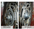
Reading the manual I think I have the left collar (as you sit on the bike) the wrong way around. However when I install that way round the disk rubs the steering column strut. Is this just a case of getting the axle seated correctly and it’ll space things out ? Will play with it tomorrow and see.Hi Guys, I've just installed my front wheel after a tyre change and it seems to be OK but I want to verify. The Left side of the bike (as per picture provided by Jheath ) doesn't gel with what I've found (IMG_1133). The diagram given says 4mm whereas I measure a lot more and it goes inward (recesses) I've attached my pictures. As you can see the Left side picture shows the shoulder to be 5.4mm from the wheel axle surface (Non ABS 2003 ST1300). I tried turning this around but it causes the Brake Disk to rub the support strut. When I turned it around it made clearance and the wheel ran free. I was then able to install the brake calipers and lock them in place and they seem to seat well. The wheel turns but has a small amount of resistance once I tightened the axle nut/hex to spec torque (I've lubed everything including bearings). The brakes seem to clamp down correctly.
My concern is that the 4mm given in the diagram does not meet what I measure. Do I have this in backwards ? Does the left Hex need to seat more to take up this slop (IMG_1136) ? .
I'd like to get confirmation (or correction) before I take it on a test run since I don't want to damage anything.
Thanks.
I think the left spacer )as you sit on the bike) is in backwards. In the shop manual it’s referred to as a collar. I have no other parts so there is no spacer or extra things that I’ve missed. The only thing I can think of is that the hexnut side of the axle (left) has to seat in further to get the correct spacing. Will try this in the morning.
Thanks. I’ll go through your process tomorrow and see if/where I’ve messed up. I suspect the clutch side collar is flipped.The point of the photo was to enable you to distinguish between the two collars and recognise which collar goes on which side. Without having to get out a caliper !
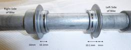
Put them on a worktop . Both collars have one side that is 10mm ish. Put that face down. Put side by side the flanges should touch be at the same height. 10mm off the work bench. That 10mm side fits against the bearing.
The other side is easy to distinguish - one is 4x bigger than the other 4mm v 16mm. The taller one fits on the axle bolt (right / brake lever ) side, with the 10.1 mm half fitting into the seal, against the face of the bearing.
Your photos. Difficult to tell, but 1132 looks as though that is a 10mm side that I can see. It certainly isnt a 4mm side.
1136 reveals that the axle bolt is protruding out of the axle bolt hole. This suggest that you might have tightened the pinch bolts before everything was aligned - which might mean that when you tightened the axle bolt, the pich bolts were stopping the axle from being pulled across.
Take you wheel out. Take the collars out. Find out which is the left and which is the right. Put the 10mm side into the wheel hub held in place by the seal.
Put the wheel back and slide the axle through. Do not tighten any pinch bolts.
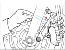
Watch the video. Note that the axle has a step on the left / clutch side. As the axle bolt is tightened, that step meets the left collar and moves it across to meet the left bearing (this is on the right hand side of the video screen). As the axle bolt is tightened more, look at the left side of the video screen. There is a big red arrow on the axle. Watch how the axle pulls across the entire hub so that the right / brake lever side bearing meets the right collar. The entire wheel assembly is then drawn tight against the right / brake lever side fork leg.
At this point the left / clutch lever fork legs has absolutely nothing to do with clamping the wheel. It is merely supporting that end of the axle. In fact the fork leg can move side to side on the axle with the wheel hub clamped firmly in place against the right hand fork leg.
Of course practicalities creep in. If you do not have a large hex driver, then you have to stop the axle from turning somehow. So when you push the axle in, make sure that you press it in firmly so that the end of the axle is almost flush with the fork leg. Then temporarily tighten the left / clutch side axle pich bolts. Then tighten the axle, then tighten the right axle bolt side pich bolts slacken the left / clutch lever pinch bolts again.
Your photo 1136 suggests that at least some of this process wasn't followed. I cannot see the flange on that photo, but it looks as though it has the shiny marks where the collar has been polished previously by the rubber seal. If the axle is tight it might also mean that you may have damaged the seal as it may have been squashed against the bearing. Maybe not if you tightened the axle with the left/clutch side pinch bolts tightened.
The next step is to fit the brakes, because you need to bounce the forks up an down while the brakes are applied. Then the left fork leg needs to be positioned so that the end if the axle is flush. If this isn't the case, as in your photo 1136, then your brake caliper which is now part of the left fork, will be pushed towards the brake disc/rotor and your brakes will bind, which will then apply the rear brakes. You need clearance between the point where the rotor passes through a narrow slot in the caliper bracket. See owners manual
Your photos 1137 and 1138 show the correct collar the correct way round. I cannot tell if the distance you are measuring is the same as the collar measurement. I don't recall whether the fork leg on the inside has a raised part of the moulding. They often do this for cast alloy - Cast a raised part so that it can be machined accurately to provide a smooth face at the correct 'height'.
Or maybe I measured incorrectly when I labelled the diagram. I only used a steel rule. I'll add a bit to the caption for that photo.
.
BTW, the reason I used the calliper is so that you could see the dimensions instead of some cock-eyed photo that might not tell the whole story.The point of the photo was to enable you to distinguish between the two collars and recognise which collar goes on which side. Without having to get out a caliper !
.
Perfect. This clears it up for me. I defo put the clutch side in the wrong way round. I thought I did but convinced myself because it made the brakes fit easily!!
BTW, the reason I used the calliper is so that you could see the dimensions instead of some cock-eyed photo that might not tell the whole story.
BTW I tried to move the left (clutch) side strut but I couldn’t get it to stop rubbing the brake disk on the strut. Will have to mess with that and see if I can move it outwards to give enough room. I’m assuming you bounce test with the pinch bolts loose and the brakes removed ? And then do the reassembly of brakes once you get everything aligned ? The reason I put it in backwards is it gave the exact spacing required for the clutch side brakes to seat properly. Pretty piss poor design by Honda TBH. They should have a collar that makes this impossible to screw up. Simple notches+tabs on one side would work!
Pretty sure the wheel is the correct way around as the direction arrow is pointing the correct way. I thought that might be the issue. Will go through it all again tomorrow with revised knowledge. Thanks for your help. Much appreciated. I’ll hopefully figure it out! I suspect bouncing the forks will free up the left side.Sorry -I'll answer the questions now.
pinch bolts - only the left side needs to be loose. Axle fully torqued and right pinch bolts tight.
I put the brakes on the bike - but if you are having issues, then that is a pain. A chock or against the garage wall.
Dont use the collar the wrong way round. The metal needs to sit against the metal of the inner race of the bearing.
Put it together following the sequence. If the caliper bracket is catching the brake disc, then there is a different problem. Have you got the wheel the right way round, for example ? Assemble it correctly. If there are still issues we'll start from there !
In the Honda Service Manual it instructs to check the clearance between the brake disc and the caliper after installation. It calls for a minimum clearance of 0.7mm, or 0.028", of clearance between the two. For discussion purposes let us agree that everything involved in installing the front wheel is installed and assembled correctly.IF the collar is correct AND the axle is flush THEN the caliper and the brake disk rotor will be in the correct position relative to each other.
You covered most every fault that could possibly be less one that thing.If none of these defects are present I don't see how the lateral positioning of the right-hand side (brake lever side) caliper and the outside face of the right-hand side brake disc can be altered if the clearance is found to be below the minimum 0.7mm specification.
May be but that wouldn't affect the clearance on the right-hand side.I've found them so flat, that the rotors scraped the SMC brackets.
The reason I am asking is because I don't have oddles of space, just a tinch. Whenever I re-install the front wheel I only have the absolute minimum clearance specified between the right-hand caliper and the right-hand disc outer face. I purchased this motorcycle new and this has been the case since day one. The first front wheel install was done by the dealer as part of the prep. I have no idea what they did or didn't do but by the time that I received it everything was in the correct position. No one has ever touched it except me since and I have never incorrectly installed the spacers.In practice I think that there is oodles of space between the caliper and the brake disc on both sides.