You are using an out of date browser. It may not display this or other websites correctly.
You should upgrade or use an alternative browser.
You should upgrade or use an alternative browser.
New bike (2016-VFR1200X), need advice on a "repair" I need to make
- Thread starter Mikedo
- Start date
- Joined
- Mar 18, 2006
- Messages
- 2,991
- Age
- 70
- Location
- Ilkley, W Yorkshire, UK
- Bike
- 2013 ST1300 A9
- 2024 Miles
- 000679
Yes, I just didn't know which wire had been selected for that purpose, and it doesn't really matter for the purpose of this diagram. It needs to be one that becomes live when the ignition key is turned to 'Ignition' and not when turned to 'Acessories only' The coil draws less than 1A and most circuits / fuses won't have a problem with that.@jfheath the solid green wire / brown wire would be a 12V power source, which may be switched on and off with the bikes ignition.
If it was me I would never use one of those quick splice devices. They can cut into the wire strands, reduce the capacity of the cable and they also expose the core to the elements so they are susceptible to corrosion and that leads to overheating and melting.
But the original poster @Mikedo acquired the bike with this already fitted. He has already indicated taking the feed from one of the quartet harness feeds instead. That cut will still need protecting though. I made my own 'quartet' harness to give me the connectors that I want in the locations that I want them. For the rear light - I have a top box spolier brake light which I wanted to convert to a tail stop light - I cut the 3 cables in the harness for the tail light (tail, brake, earth) and inserted a new 3p male/female connecter to rejoin them - with an additional female connector for the spoiler. A couple of diodes and a resistor and I have an always-on LED tail light which comes on brighter when the brakes are applied.
(Just for reference, that modification for the top box tail light is here. Post#42. 28 Nov 2021)
Last edited:
If you want to check fuse/relay sizing or perhaps decide what size relay you need for this application, see below:
1. The 2amp fuse used in the coil circuit... you'll need to know the curent draw of relay coil as the fuse needs to carry 1.25 times that current. You'll get the coil current from relay specs.
2. To size the relay you'll need to know the current pulled by the lights as the relay contacts will carry that times 1.25 as well. Then, you can select the closest size up relay available. The current for the lights should be in the lights specs or labeled on the lights.
As a general note, the current can also be measured with your meter set to Amperes and meter inserted in the circuit (not parallel like when you measure volts).
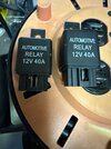
While I recognize this is something that could be done, I'm running with the fact that SW Motech put more thought in it than I will. Hopefully they were correct in assigning a 12V 40A relay to the task. My musings that it seems excessive are based perhaps on ignorance on this topic.If you want to check fuse/relay sizing or perhaps decide what size relay you need for this application, see below:
1. The 2amp fuse used in the coil circuit... you'll need to know the curent draw of relay coil as the fuse needs to carry 1.25 times that current. You'll get the coil current from relay specs.
2. To size the relay you'll need to know the current pulled by the lights as the relay contacts will carry that times 1.25 as well. Then, you can select the closest size up relay available. The current for the lights should be in the lights specs or labeled on the lights.
As a general note, the current can also be measured with your meter set to Amperes and meter inserted in the circuit (not parallel like when you measure volts).
They, SW Motech, may also have just picked the cheapest relay they could find. The fact it has ZERO markings or parts numbers on it that I can look up leads me to think this.
I've ordered one that looks the same and has the same values for fitment. The other half of the part that plugs in must fit to work again. Or I then have to get into re-wiring the part/plug, and I'd just as soon not do that.
Sounds like a plan, I was actually going to suggest using the existing socket if a compatible relay can be found. However, looking at your pic of the socket I believe I see a contact that is open more than the others and may create problems when plugging in the new relay, but that remains to be seen.
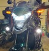
UPDATE: The lights are on (but perhaps nobody is home).
I got the relays I ordered from Amazon today and I immediately went and tried one out. Results below.
Now I just have to figure out how to wire it properly to use this switch.
The dash has a blank for it. https://www.africa-twin-shop.com/en...ditional-fog-light-switch-08v04-mjp-g50a.html
Also, thanks to everyone for their suggestions and help with this project. Now I can put it back together and worry about sending away the ECU for a flash over the winter...
Attachments
Mike. I'll call tomorrow.
I used this Posi-tap to connect the relay to the trigger wire. I think it is less invasive than the connector you have. Been on there for over 40,000 miles now.
Customer Installation- Posi-Tap Instructions
Tapped Wire, Wire Stripper, Patco
www.posi-products.com
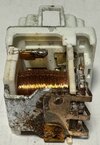
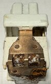
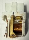
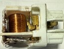
One more follow-up on the relay. I cut it open and found some corrosion. See photos.
I don't think any wires are broken, but there was a lot of resistance to the armature (is that the right word) moving when I pushed it. So likely the rust was inhibiting the function. I finally put it all together and rode it today. Lights worked fine and throw a lot of light (at least in the backyard when I parked it).
I don't think any wires are broken, but there was a lot of resistance to the armature (is that the right word) moving when I pushed it. So likely the rust was inhibiting the function. I finally put it all together and rode it today. Lights worked fine and throw a lot of light (at least in the backyard when I parked it).
Attachments
Interesting, I wonder if the location of the relay makes it susceptible to moisture ingress. Maybe apply some dielectric grease to it.
Best to see if you can find a new one and replace it. While it's working now, that corrosion will just continue. The resistance will generate more heat in the wires & relay and it will fail again.
Get new relay....... try your local Napa, or other auto parts supply..... or .......
Mike did get a new relay to match the old one. He just did a post-mortem on the old relay to see why it failed.
1) Yes, new relay, and a spare, already obtained.
2) Yes, will be mounted in downward orientation to hopefully avoid a repeat.
3) Yes, dielectric grease added to new fitting before mounting.
I think the water was chasing down the wiring from the switch location near the handlebars and ignition. Wind driven maybe. I thought about sealing the two ends of the protective tubing to help reduce the effect. I noticed water come out of this tubing when I removed and let it hang off the side of the bike. Maybe just the top needs sealing. If you look at post #20 picture 5413 you see the downside end of the cable and cover just above the relay. This is where the water poured out of when I inverted the whole thing. Water could still chase down the length of the protective outer sheathing though too.
Normally the wires sit and create a loop or "P-trap" so to speak, but I feel the wind may be pushing small amounts along the wires and then to the relay. Or I'm wrong and it is ingressing another way, but I've done what I can to combat it.
Have a great day, and again thanks for all the help and suggestions.
Andrew Shadow
Site Supporter
Consider electronic relays. Besides not having any moving parts that can seize they are available in fully waterproof enclosures. There are different amperages sizes available. The micro relay, for example, is much smaller than the traditional automotive relay so the options of where you can install them are more numerous.
Last edited:
- Joined
- Mar 18, 2006
- Messages
- 2,991
- Age
- 70
- Location
- Ilkley, W Yorkshire, UK
- Bike
- 2013 ST1300 A9
- 2024 Miles
- 000679
Those particular relays are normally housed in a rubber cap - only open at the bottom. The design of the cap allows them to be suspended vertically, wires down, on an upward pointing metal bracket. Nevertheless, the corrosion is there and you have replaced it. Not usualy though, but I suppose after 20 years.....
Share:


