I may need to. Keep reading.If you need a hand I am only a few minutes away and have a bit of knowledge .
You are using an out of date browser. It may not display this or other websites correctly.
You should upgrade or use an alternative browser.
You should upgrade or use an alternative browser.
New bike (2016-VFR1200X), need advice on a "repair" I need to make
- Thread starter Mikedo
- Start date
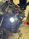
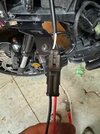
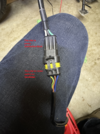
At least I know the lights do work when wired directly to battery. The light kit wires that run to the fog lamps are black and white. The wiring for my new connectors run black and red (see photos).
I used household wire to make my franken-connector and put black to black and white to red. When I first connected to battery I got nothing. So I switched positions and the lights came on...yeah!
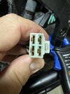
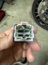
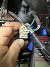
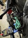
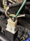
I did some additional testing as well. See photos for parts and colour descriptions.
At the rocker switch there were 11 volts across the blue and brown (reddish) always. There were 11 volts across the yellow only when the switch was "on".
At the first connector below the switch there were 11 volts across all pins (three), always.
At the two pin connector to the left fog lamp there were 0 volts. I didn't bother testing the right one I felt assured it would be 0 as well.
The green switched power comes from a factory connection and tapped from where the power goes to the 12 volt cigarette outlet (factory installed).
I was still unable to pry open what I (we've) been calling a relay. I'm not sure it is, it seems to perhaps function as a distribution block? And it did not jiggle or react when power or switch operated.
Attachments
-
 left fog light.jpg142.6 KB · Views: 26
 -
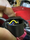 IMG_5418.jpeg88.3 KB · Views: 19
 -
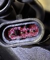 IMG_5420.jpeg134.1 KB · Views: 17
 -
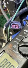 IMG_5422.jpeg99.2 KB · Views: 18
 -
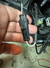 IMG_5428.JPG79.2 KB · Views: 20
 -
 IMG_5427.JPG22.6 KB · Views: 23
 -
 IMG_5433.JPG81.7 KB · Views: 27
 -
 IMG_5429.JPG76 KB · Views: 31
 -
 Fog lamp switch and connector.png1.2 MB · Views: 30
Last edited:
From your pics:
1 - (last pic) the Yellow/Green stripe becomes White at the connector. Can you trace the White make sure it reaches the relay socket, then measure 12V to ground at relay socket, on "that White" with light switch on and connector plugged in? Should 12V be present on that White wire at relay socket, then you're getting signal to turn relay on.
2 - (pic before last) - how many White wires you have there? I'm thinking one White coming from the connector in Line 1; one White coming from Battery; and one White going out to lamps. Can you remove one battery lead and set your meter on Ohms or continuity, then probe all Black wires at socket to Ground for continuity? Then, connect battery back in, set meter on Volts DC, measure for 12V at socket, the other 2 White wires (leave the one tested in Line 1 out). You should have 12V on one of the Whites.
The green never makes it into the socket. It comes from/ and goes to the switch from point of connection with power from the "switched power source" on the bike.From your pics:
1 - (last pic) the Yellow/Green stripe becomes White at the connector. Can you trace the White make sure it reaches the relay socket, then measure 12V to ground at relay socket, on "that White" with light switch on and connector plugged in? Should 12V be present on that White wire at relay socket, then you're getting signal to turn relay on.
2 - (pic before last) - how many White wires you have there? I'm thinking one White coming from the connector in Line 1; one White coming from Battery; and one White going out to lamps. Can you remove one battery lead and set your meter on Ohms or continuity, then probe all Black wires at socket to Ground for continuity? Then, connect battery back in, set meter on Volts DC, measure for 12V at socket, the other 2 White wires (leave the one tested in Line 1 out). You should have 12V on one of the Whites.
I cannot probe anything in the socket at all, yet. I have been unable to unclip that socket yet. That socket only has white and black lines in it. I may pull it all out of the bike later this week (minus the lamps), to see if I can better attack it on the bench, I've been prying at it pretty hard, but cannot make it separate.
If that is a relay, then it is not functioning, or at least not showing any outward sign of function.
IO notice in their parts list they did not ship the relay, nor mention it....BUT (see next image) the install speaks to a relay. So, a relay it is.
It appears to be wired in accordance with this. So maybe the relay is not working and needs replacing. The bike has damage right where the relay was zip tied to the plastic support (now repaired, but was broken under the fairing.
Where and how do I get a new relay?


I cannot probe anything in the socket at all, yet.
What I do... I use a pin needle inserted along the wire into the socket (one wire at a time) until it stops and measure from there (back-probing the socket). I saw the diagram, made a reference to it in one of the posts. And you may not need a relay, it sounds like you're not getting the trigger signal to turn on, but will see if that's true after back-probing.
Added - can you see a securing feature on the socket or the relay that can be pried open with a tiny screwdriver blade? Is the channel on the front face in your pic that feature? Can you see a snap in there?
Last edited:
You can pick up a relay at Princess Auto or Canadian tire.
Something like this but you don’t need 40 amps
 www.canadiantire.ca
Something like this but you don’t need 40 amps
General PDP Template
- Joined
- Mar 18, 2006
- Messages
- 2,991
- Age
- 70
- Location
- Ilkley, W Yorkshire, UK
- Bike
- 2013 ST1300 A9
- 2024 Miles
- 000679
Right - the diagram helps a bit. The 2A fuse is as it should be - that is on the lead that taps into your original power lead to provide a trigger voltage to turn the relay on. A 1A fuse would do for that, but 2A is OK. That wire will go up to the rocker switch and then back down to one of the the relay terminals.
That diagram helps to understand what you have. I cannot work out what colour wires you have, and I cannot bring myself to draw a circuit diagram with a green positive wire !!
But I think that this is what you are looking at - or something very similar. I've tried to guess what is inside the protective sheaths. Your diagrma only shows the combined leads - so it is not much use for fault finding. I hope that this might help. Ive tried to draw things in roughly the same position. The single cables have a white centre. It is not two cables. Its space to colour in the actual cable colour !!

Check it through:
On the left, the power supply for the trigger coil comes from one of those horrible cable splice devices. It comes from a power line that turns on when the ignition is on.
It is fused with a 2A fuse. That is all that line needs - the coil inside the relay draws less than 1A. It is then conencted to a switch. When the switch is on, that passes 12v to one side of the coil. The other side of the coil is connected to the battery earth -and that completes the circuit. The colid has current flowing through it, which creates a magnetic field and that causes the other two contact in the relay to conenct together.
The power from the battery flows through the 5A fuse to one of the switch terminals on the relay . The relay is switched on by the blue circuit. and that sends power to both lamps. They may be connected both on the same relay terminal or joined together in the wiring harness later.
The black lines on the diagram show the connection to the battery negative terminal. THis is shown connected to the relay, and then another wire connects it to the two bulbs.
So that completes the circuit for the headlight.
When the switch is off or the ignition is off. There is no magentic field in the relay coil, so the two contacts separate and turn the headlight circuit off.
I suggest that you try to work out what colour wires are which part of the diagram and label them or colour it in. Then find out which part of it is broken.
That diagram helps to understand what you have. I cannot work out what colour wires you have, and I cannot bring myself to draw a circuit diagram with a green positive wire !!
But I think that this is what you are looking at - or something very similar. I've tried to guess what is inside the protective sheaths. Your diagrma only shows the combined leads - so it is not much use for fault finding. I hope that this might help. Ive tried to draw things in roughly the same position. The single cables have a white centre. It is not two cables. Its space to colour in the actual cable colour !!

Check it through:
On the left, the power supply for the trigger coil comes from one of those horrible cable splice devices. It comes from a power line that turns on when the ignition is on.
It is fused with a 2A fuse. That is all that line needs - the coil inside the relay draws less than 1A. It is then conencted to a switch. When the switch is on, that passes 12v to one side of the coil. The other side of the coil is connected to the battery earth -and that completes the circuit. The colid has current flowing through it, which creates a magnetic field and that causes the other two contact in the relay to conenct together.
The power from the battery flows through the 5A fuse to one of the switch terminals on the relay . The relay is switched on by the blue circuit. and that sends power to both lamps. They may be connected both on the same relay terminal or joined together in the wiring harness later.
The black lines on the diagram show the connection to the battery negative terminal. THis is shown connected to the relay, and then another wire connects it to the two bulbs.
So that completes the circuit for the headlight.
When the switch is off or the ignition is off. There is no magentic field in the relay coil, so the two contacts separate and turn the headlight circuit off.
I suggest that you try to work out what colour wires are which part of the diagram and label them or colour it in. Then find out which part of it is broken.
And the relay is now taken apart. Shows a bit of water intrusion and some corrosion.
Is the relay now kaput? I got no continuity across any of the pins (4) in any order.
I did get some continuity from the plug. One black to one white whistled at me. From battery to switch.
Is the relay now kaput? I got no continuity across any of the pins (4) in any order.
I did get some continuity from the plug. One black to one white whistled at me. From battery to switch.
Attachments
Last edited:
Your diagram is close. Perfect for the lamps and battery, configured a little different, but explains it the same. The line with the 5A fuse is white, not red. There is no red in fact, except for the short bit between the switch and the first three pin connector.Right - the diagram helps a bit. The 2A fuse is as it should be - that is on the lead that taps into your original power lead to provide a trigger voltage to turn the relay on. A 1A fuse would do for that, but 2A is OK. That wire will go up to the rocker switch and then back down to one of the the relay terminals.
That diagram helps to understand what you have. I cannot work out what colour wires you have, and I cannot bring myself to draw a circuit diagram with a green positive wire !!
But I think that this is what you are looking at - or something very similar. I've tried to guess what is inside the protective sheaths. Your diagrma only shows the combined leads - so it is not much use for fault finding. I hope that this might help. Ive tried to draw things in roughly the same position. The single cables have a white centre. It is not two cables. Its space to colour in the actual cable colour !!
Check it through:
On the left, the power supply for the trigger coil comes from one of those horrible cable splice devices. It comes from a power line that turns on when the ignition is on.
It is fused with a 2A fuse. That is all that line needs - the coil inside the relay draws less than 1A. It is then conencted to a switch. When the switch is on, that passes 12v to one side of the coil. The other side of the coil is connected to the battery earth -and that completes the circuit. The colid has current flowing through it, which creates a magnetic field and that causes the other two contact in the relay to conenct together.
The power from the battery flows through the 5A fuse to one of the switch terminals on the relay . The relay is switched on by the blue circuit. and that sends power to both lamps. They may be connected both on the same relay terminal or joined together in the wiring harness later.
The black lines on the diagram show the connection to the battery negative terminal. THis is shown connected to the relay, and then another wire connects it to the two bulbs.
So that completes the circuit for the headlight.
When the switch is off or the ignition is off. There is no magentic field in the relay coil, so the two contacts separate and turn the headlight circuit off.
I suggest that you try to work out what colour wires are which part of the diagram and label them or colour it in. Then find out which part of it is broken.
The only wires in most sheaths are black and white. To/from battery and plug into relay.
From plug/relay to lights with a splitter, just black and white again. Three black wires are combined in one slot of the relay.
To/from the switch is black, white, and green, picked up from the power source. The green does not go into the relay.
Attachments
Last edited:
I got it apart. But thanks. I may have to put together again and pin it, but I think the relay is shot.What I do... I use a pin needle inserted along the wire into the socket (one wire at a time) until it stops and measure from there (back-probing the socket). I saw the diagram, made a reference to it in one of the posts. And you may not need a relay, it sounds like you're not getting the trigger signal to turn on, but will see if that's true after back-probing.
Added - can you see a securing feature on the socket or the relay that can be pried open with a tiny screwdriver blade? Is the channel on the front face in your pic that feature? Can you see a snap in there?
Looks like a 12 V 40 Amp model. Seems a bit big for the job....
Last edited:
- Joined
- Mar 18, 2006
- Messages
- 2,991
- Age
- 70
- Location
- Ilkley, W Yorkshire, UK
- Bike
- 2013 ST1300 A9
- 2024 Miles
- 000679
I was trying to use colours that you didnt have. Because I could not tell where (say) the green yellow wire goes to. Or the three whites.
So its a physical diagram for you to colour in with the wires that you have !
Theres one difference that I just spotted. Your rocker switch has three wires. Do your lights have hi / lo beam ?
In which case - are they intended to be always on ?
Whatever, the general layout is there - you'll be able to modify it when you test continuity in unplugged connectors end to end.
With the relay unplugged you should get a very low resistance - ohms - when you probe one pair of terminals at the bottom of the relay. Set the meter to ohms for very low levels (ie not k.ohms or meg.ohms).
Good picture and wire labeling. So, at the socket, the black is groung/battery negative. The white coming from switched power is for triggering and goes to relay coil. Can you measure any ohms on the relay between those 2 pins? If not, relay is shot.
Note - you said there's no resistance between pins in any order, just want to confirm I'm on same page.
Note - you said there's no resistance between pins in any order, just want to confirm I'm on same page.
Last edited:
Theres one difference that I just spotted. Your rocker switch has three wires. Do your lights have hi / lo beam ?
There's 3 wires to the switch as it's illuminated.
First wire is power in, splits internally.
When "on" the power goes thru the switch bulb and out the 2nd wire to ground.
When "on" the 3rd wire feeds the relay to turn it on.
That's why the switch was illuminating but the relay wasn't turning on the lights.
Last edited:
Check with the switch ON, there should be 12V coming on the white wire to the relay (you said 11V but you had the ignition on so understandable). If you have voltage, and the black wire is ground, then the relay should trigger..... I'd get a new relay based on your test of no continuity in the trigger coil. Later you can open up the relay and likely find the fine wire to the coil has a break in it...
- Joined
- Mar 18, 2006
- Messages
- 2,991
- Age
- 70
- Location
- Ilkley, W Yorkshire, UK
- Bike
- 2013 ST1300 A9
- 2024 Miles
- 000679
I got it apart. But thanks. I may have to put together again and pin it, but I think the relay is shot.
Looks like a 12 V 40 Amp model. Seems a bit big for the job....
The relay looks like the standard one that Honda used to use. If so, I've got one here in front of me. The relay connection (terminal) end of the relay (disconnected from its mate) measures 21mm x 14mm and has 4 terminals arranged 2x2
Placed on the desk without the mating part, with the terminal facing you and the latch on the top the two terminals on the right, one above the other, are for the trigger coil. This measures around 100 ohms. +/- 5 (I've got two here and they are lsightly different). If you put 12v across those two, the relay should click. Those two spade terminals are a dull silver colour.
The two terminals on the right are copper coloured. They should show infinite resistance when the relay is turned off, and zero resistance when 12v is put across the two terminals on the right.
The part number is Misuba RC-22-8 and mine have the characters 3YP at the bottom

Last edited:
The relay looks like the standard one that Honda used to use.
Looks similar and it matches the wiring on his socket wiring picture, confirming pins 1-2 are the coil.
- Joined
- Mar 18, 2006
- Messages
- 2,991
- Age
- 70
- Location
- Ilkley, W Yorkshire, UK
- Bike
- 2013 ST1300 A9
- 2024 Miles
- 000679
Ok so you have 3 black lines coming out of the relay to the headlights. I can understand why you would have two, but why three - where does the other go ??
If the black leads are top left when looking at the cable - you have a white lead - that should be going to the 5A fuse from the battery.
The green lead doesn't touch the relay. That should be coming from the splice gadget and go up to the switch. It may be split to provide power for the rocker switch light bulb ?
A lead should come back from the rocker switch to one of the right hand conenctors on the relay. (That looks as though it is one of the three whites).
Another white should be going to earth or battery.
There should be another lead coming from the lights to complete the circuit to the -ve post of the battery ie earth.
So it looks as though you have a white lead going to earth and another white lead going to the battery. Hmmm. Excuse me while I go an utter some profanities.
I think that you need to disconnect the relay and find out where each of those white leads go. When you have a matching pair then label them - coloured cable ties or coloured insualtion tape.
Use the resistance meter on your multimeter. Probe one end and locate the other end - not plugged into anything else and test it. It should show a resistance. Keepp playing hide and seek until you have every terminal paried up with its other end.
Mark them on that diagram as you find them - along with how you have coloured/labeled them - lets see what we have.
Just assume that everything is wrong and it needs redoing. Don't assume anything is correct until you have proved that it is correct. Remember that if you replace the relay - you still have a circuit which managed to blow a 2A fuse. So something somwhere is definitely wrong. That fuse feeding that trigger coil should never have been able to blow. Something is short circuited and before you even plug that relay back in, we need to find out where it is - or better find out what is right and what is wrong, and redo the wrong bits.
I have one other question. There should be two earth leads. One from the trigger coil on the relay. One from the headlamps. Where are they in your wiring ? I may have missed it, but I don't think that you have mentioned them.
Last edited:
I can understand why you would have two, but why three - where does the other go ??
Looking at the picture of the socket... there's one Black coming from battery, one Black going out to lights, one Black coming from light switch. They used the socket as a ground point, only (external to this circuit) ground is at battery negative.
Added: same with the Whites: one to coil, one to battery and one to lights.
Last edited:
- Joined
- Mar 18, 2006
- Messages
- 2,991
- Age
- 70
- Location
- Ilkley, W Yorkshire, UK
- Bike
- 2013 ST1300 A9
- 2024 Miles
- 000679
 OK I've worked out which white lead must be which.
I've put leads that are next to each other in the protective sleeves, next to each other in the diagram.
I cant show white leads, and one with a black outline put to much black on the drawing, so I've used a coloured outline to identify the white leads.
The red outlines white lead comes direct from the battery.
The blue outlined white lead is the one that is switched on by the relay.
The green outlines white lead is the one that is connected to earth for the light in the switch.
The black leads are all earth
The brown lead on the left is whatever the green lead is spliced into.
I hope this helps !!
Thinking out loud here, but... if you use a paperclip or a piece of wire and jumper the 2 Whites at the bottom of the socket below (White coming from battery jumpered to White going out to lights, notice RED jumper) you should have the lights turn on - that will prove the lights circuit is fine.

Careful if you do this to make sure you jumper the correct wires. For added safety turn lights switch off.

Careful if you do this to make sure you jumper the correct wires. For added safety turn lights switch off.
Share:

