ST1300 Heated Grips

On this side of the pond we would call that 'potting'.

Yep. In the service a lot of our gear was 'weatherproofed by potting in and putting in a somewhat water resistant contained. One dead always dead. *Kind of cool to pull apart something and have a rectangle/square/whatever. Usually it was opaque but a couple times it was amber and you could see most of the components. Pretty cool.
 
Good point!
According to the service manual, the charging voltage shall be between battery nominal (12V) and 15.5V @ 5000 rpm. Quite a large range, indeed.
Note that I would be much more worried if I saw 15.5V on the battery terminals. Ouch! Here goes the battery and bulb life…

Before putting the bike away for winter, I did a quick voltage check with the engine running. I installed a small dedicated 12V voltmeter to monitor the system voltage, (the voltmeter was checked and confirmed for calibration) placed in such a way that I could see the reading during riding, but not connected directly to the battery terminals. It was connected to a similar circuit has for the grip controller.
It was quite steady @ 13.7V (±0.1V), except when the flashers were activated. Then it was all over the place.
First scary symptom!
The rest is described in the previous post.
Understood that I have to push the investigation further. Mainly, checking the battery voltage @ 5000 rpm.
Waiting for a relief in cold temperature to bring the bike out for a quick test cession, in the car shelter…
More to come...
 
Just as a personal reference. I check my charging voltage every year when I fire the bike up in the spring. It is always tests at 14.1 or 14.2 volts even at idle. There is very little variation based on RPM.
 
Just as a personal reference. I check my charging voltage every year when I fire the bike up in the spring. It is always tests at 14.1 or 14.2 volts even at idle. There is very little variation based on RPM.

Thanks for the head’s up.
It makes sense, since the alternator is a “car” type with an inboard precision regulator*. So, it brings me to about -0.4V offset from your reading, and since the 13.7V value was stable and wasn’t taken at the battery terminals… it is probably OK.
With the new and permanently installed voltmeter reading the battery directly, it will be easy to monitor the voltage fluctuations during operation.

* I was quite surprised to see the 5000 rpm requirement to test the charging voltage, and, of course, the extremely wide acceptable range. Which doesn't make sense with such a charging system.
Remains of older systems…?
 
I have always checked mine ST1300 charging volts with a full or nearly fully charged battery as I charge it before putting it back in. I suppose in the extreme with a very weak battery the regulator might ramp up much higher to meet the need but I have never seen any significant variance from 14.2 or so volts.
 
Thanks for the head’s up.
It makes sense, since the alternator is a “car” type with an inboard precision regulator*. So, it brings me to about -0.4V offset from your reading, and since the 13.7V value was stable and wasn’t taken at the battery terminals… it is probably OK.
With the new and permanently installed voltmeter reading the battery directly, it will be easy to monitor the voltage fluctuations during operation.

* I was quite surprised to see the 5000 rpm requirement to test the charging voltage, and, of course, the extremely wide acceptable range. Which doesn't make sense with such a charging system.
Remains of older systems…?
if you think the alternator is starting to fail check for a/c voltage . should be .5 or less.
 
I have always checked mine ST1300 charging volts with a full or nearly fully charged battery as I charge it before putting it back in. I suppose in the extreme with a very weak battery the regulator might ramp up much higher to meet the need but I have never seen any significant variance from 14.2 or so volts.
Wouldn’t a discharged battery lower the system voltage? A battery static testing at 12.2 needs approximately 13.2 volts to charge normally. As battery charge comes up with time the system voltage would rise accordingly from 12.2 and peak in the 14.1 to 14.6 range. At least I think that is how a regulator “pushes” charge into a conventional lead acid battery. >15.5 volts would indicate a failure of the regulator. I could well be wrong, but I believe this is how it works.
 
Wouldn’t a discharged battery lower the system voltage? A battery static testing at 12.2 needs approximately 13.2 volts to charge normally. As battery charge comes up with time the system voltage would rise accordingly from 12.2 and peak in the 14.1 to 14.6 range. At least I think that is how a regulator “pushes” charge into a conventional lead acid battery. >15.5 volts would indicate a failure of the regulator. I could well be wrong, but I believe this is how it works.
You are right on.
15.5 volts would kill the battery in the short term, and all the bulbs in the long run.

Here is a quote from The Battery University (A reference in that domain that I often used during my active years) Check the embeded link for more details.

"The correct setting of the charge voltage limit is critical and ranges from 2.30V to 2.45V per cell. Setting the voltage threshold is a compromise and battery experts refer to this as “dancing on the head of a pin.” On one hand, the battery wants to be fully charged to get maximum capacity and avoid sulfation on the negative plate; on the other hand, over-saturation by not switching to float charge causes grid corrosion on the positive plate. This also leads to gassing and water-loss."

In other terms, you have to limit sulfation AND grid corrosion. Two opposite requirements. It is up to the charger designer to conceive a circuit that will best fit his targeted application.

Unfortunately, car or motorcycle charging systems are not that intelligent and they don't need to be. These are NOT standby systems, where long periods of standby are followed by short bursts of high discharge rate. (Ex.: back-up systems used to power critical loads in case of grid failure, my domain of expertise).
However, in our case, for long time reliability you have to choose the best compromise. This translate to a range of 13.8V to 14.7V, averaging to 14.25V. Quite close to the reading our friend Andrew found on his ST.
Good design Honda!!

if you think the alternator is starting to fail check for a/c voltage . should be .5 or less.

That is an easy check, when you have the right equipment, which I do. These are 3 phase alternators and each phase voltage and current peaks can be extracted.
If one is uneven compared to the other one, then you have your answer.
Another check on my check list, if the alternator voltage is out of spec.
I can't see how you can do that with the diodes in a bridge configuration to smooth out voltage peaks. And you don't have a a/c volt meter?
 
I'm a bit of a noob to the ST bikes but I swear I recall folks mentioning a spot around the upper fairing/cluster area where multiple ground wires come together. Seems like a good place to verify proper connection.
 
Wouldn’t a discharged battery lower the system voltage? A battery static testing at 12.2 needs approximately 13.2 volts to charge normally. As battery charge comes up with time the system voltage would rise accordingly from 12.2 and peak in the 14.1 to 14.6 range. At least I think that is how a regulator “pushes” charge into a conventional lead acid battery. >15.5 volts would indicate a failure of the regulator. I could well be wrong, but I believe this is how it works.
I also have never checked mine under conditions of having a very badly discharged battery or a defective battery, so maybe. The voltage on mine decreases to the nominal 14.1 or 14.2 charging volts it always outputs as the battery returns to full charge after suffering a discharge load such as starting the engine. There isn't much variance either. It may go from 14.25 or 14.3 back down to 14.1. Nothing like modern systems where the voltage swing is very substantial.
 
I can't see how you can do that with the diodes in a bridge configuration to smooth out voltage peaks. And you don't have a a/c volt meter?

What you are reading, with your voltmeter in AC mode, is the ripple over the average voltage. This ripple is inherent when charging a battery with a rectified AC source. Single or 3 phase
See third graph in the attached image.
However the measurement with a voltmeter (AC), while it is a good way, could hide important information by averaging the reading. When you have a precision bench top digital scope, you can actually see what’s going on. If one phase, out of the 3 phases, is behaving differently you will catch it right away. Measurements could be done in voltage or current mode.
I do have this equipment. (Yokogawa DL1520) and I will use it if needed in case of alternator malfunction.

Cheers

I'm a bit of a noob to the ST bikes but I swear I recall folks mentioning a spot around the upper fairing/cluster area where multiple ground wires come together. Seems like a good place to verify proper connection.

Yah, ground connection…
It took me a while to find out where the connections are.
For the ground connections, the wiring diagram is quite clear on this point. (Based on 2003 wiring diagram, but the 2006 seems to be similar)
Unless the device is directly screwed on the engine (ECT, Neutral switch, Oil pressure, knock sensors, spark plugs, alternator, starter) all other ground connections are directed to a single point. (upper right in the attached picture) And this single point is situated on the frame, under the rear of the fuel tank. Not an easy access.
I checked for corrosion or loose connections on this single point. Everything was clean and solid. No problem there.
Note that the battery (-) is connected to the engine through the starter.
 

Attachments

  • 3 phase full wave rectification.jpg
    3 phase full wave rectification.jpg
    109.3 KB · Views: 8
  • Ground Stuff.jpg
    Ground Stuff.jpg
    102.9 KB · Views: 9
...... all other ground connections are directed to a single point.

And this single point is situated on the frame, under the rear of the fuel tank.
There are two other main ground connectors that cause problems much more often than the one at the rear of the fuel tank. You might want to have a look at them as well even if for nothing else but preventative maintenance.
One is a white connector just above and ahead of the left-hand cylinder head under the fairing. The other is a yellow connector located behind the right-hand headlamp.

All of the ground connections for the front half of the motorcycle go through one or both these connectors. Poor connectivity at either one of these causes a whole host of strange problems. The white one on the left-hand side being the most common ground failure point, most often damage related to overheating due to corrosion.
 
Surely, I will look at this more deeply.
I have already checked a few of them. The ones that were easily accessible. Mainly the ones over the left cylinder head, directly involved with the 2 pins “white” connector, (quartet connector group aka the option connectors) where the grips controller was connected. Nothing found. With the controller active, I measured the voltage drop through all the connections that are involved and easily accessible. Again things were good.

During my investigation, I noticed that one or two runs (wire) in the wiring diagram handled most of the ground connections other than the ones directly connected to the engine. And no indication on how all this is connected together. Except for the common ground point… and a lot of splices. Scary!
Obviously, if there is something failing in these “runs”, it could be anything.
Now, do you want to dig into this mess while the bike is still running strong? Not yet for me.
Hence the “bypass surgery” from the grips controller.

Do you have any idea where I could find the real “2006” wiring diagram?
 
The one on the left-hand side above the cylinder head that I was referring to is a 24 pin white connector, not a two pin. It is is part of the main harness, not the quartet harness. It has a ground wire in it that is often found to have overheated and causes a poor connection. Have a look at the below thread. It also shows how to bolster the ground circuit which is a good idea as preventative maintenance. The original ground path in this connector does not have to be disabled, just another ground path added to it to help it out.

Have a look at the first post of the below thread.

Fixed my electrical problem (headlights, dash lites,horn, turn signals, windshield)


Do you have any idea where I could find the real “2006” wiring diagram?
2006 ST1300 ABS Wiring Schematic attached.
 

Attachments

  • Wiring Schematic 2006 ST1300 ABS - R7.pdf
    372.2 KB · Views: 7
Last edited:
The one on the left-hand side above the cylinder head that I was referring to is a 24 pin white connector, not a two pin. It is is part of the main harness, not the quartet harness. It has an ground wire in it that is often found to have overheated and causes a poor connection. Have a look at the below thread. It also shows how to bolster the ground circuit which is a good idea as preventative maintenance. The original ground path in this connector does not have to disabled, just another ground path to it to help it out.

Have a look at the first post of the below thread.

Fixed my electrical problem (headlights, dash lites,horn, turn signals, windshield)


2006 ST1300 ABS Wiring Schematic attached.
Oups! You misunderstood me. I started to check at the 2 pins white connector where the grips controller is connected down through any connectors that were in the path until it was too heavy to continue. Which include a kind of big connector. Where I stopped there. Can’t remember the exact pin count of the connector. I am away from the bike now, so can't check.
There was no oxidation, no overheating and the voltage drop was close to zero.
But I might have missed something
Many thanks for the wiring diagram. And I will check the proposed thread. Seems interesting at first.
I like the idea of bringing a beefier ground locally to the circuit. I would certainly do it. Honda has been cheap on copper on these bikes.
Now it’s time to slow down and enjoy the Holidays.
Cheers!
 
Last note on the heated grips failure.
I finally got a chance to check the ST charging system a few weeks ago. Between two snow storms…
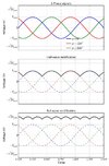
The charging system began with a nice 14.3V at the battery. Good. Checked the ripple with my scope. All phases checked present. Very good! So where’s the problem?
A design flaw?
Since the alternator is installed inside the “V” and provides a built in negative voltage temperature compensation, as the engine warms up to operating temperature, standing still in the driveway, the voltage starts to lower, following the increase of the engine temp.
Here it is, the output voltage of the alternator is quite influenced by the engine temperature. This changes everything, especially if you are moving at a low pace or in a stop & go traffic. The voltage could drop into the middle to low 13V. Independent of the ambient temperature surrounding the motorcycle. That, combined with the drop in voltage through the wiring, brought my heated grip outside the operation range.

This is the situation when I noticed the problem that started the whole process. Basically, the ambient temperature was too warm and I was caught in a very slow traffic. I just checked my heated grips… for fun. :rolleyes:

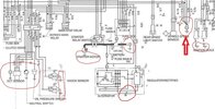
So, I am keeping the mod, which eliminates most of the voltage drops. Moreover, I went full on, and I checked for the killing green crusty on every power connector. And yes, there were some. Not extreme, but all have been deoxidized and lubricated.
I also doubled the “crazy” undersized ground run at the big white (natural) connector.

Ready, right on for the start of the too short motorcycle season… in Canada/Québec.

Everybody, thanks for your support!

IMG_2054 (Medium) Circle.pngIMG_2055 (Medium).pngIMG_2060 (Medium) Cropped Circled.jpgIMG_2105 (Medium).JPGIMG_2110 (Medium).JPG
 
Back
Top Bottom