You are using an out of date browser. It may not display this or other websites correctly.
You should upgrade or use an alternative browser.
You should upgrade or use an alternative browser.
Article [13] ST1300 - GPS / Radio / Radar Dash Mount
- Thread starter TXRoadRash
- Start date
That's nice. You're looking through the screen? Try taping a wind sock over the camera with a cut out for the lens. Might help with the wind noise. (not speaking for experience, just thinking outside of the box)
Little late to the party
Too cheap and lazy to order a migsel mount
So I fabricated my own
All aluminum, tig welded

Sent from my SM-G965U using Tapatalk
Too cheap and lazy to order a migsel mount
So I fabricated my own
All aluminum, tig welded

Sent from my SM-G965U using Tapatalk
Welcome to the forum.Little late to the party
Too cheap and lazy to order a migsel mount
So I fabricated my own
All aluminum, tig welded
Sent from my SM-G965U using Tapatalk
Good job on fabricating your own dash shelf.
corky51
loST
Very well done. Mine isn’t any near as fancy, but it too works. I took a screwdriver keeper from Canadian tire, a couple metalstrips for reinforcement, and a piece of garbage can lid for water deflector. And trailer wiring kit x2. I hope my photos show my shelf. Been on ST for 5 years now, hasn’t moved, or got wet. My nuvi and speed indicator stay dry.
Attachments
corky51
loST
corky51
loST
I place a sandwich bag over my nuvi, but it hasn't got wet yet.
That works too, I made to only mount one thing, not sure how much weight the dash can take.
I happen to do metal fabrication and have rooms at home for mine
Sent from my SM-G965U using Tapatalk
I happen to do metal fabrication and have rooms at home for mine
Sent from my SM-G965U using Tapatalk
After looking at numerous dash shelf and dash mount designs for the ST, and after attempting a (failed) group buy on the Migsel mount, I decided to forego the expense of an aftermarket bracket or mount and fabricate one from materials that I had on hand and a couple of ram balls purchased online.
After 10 years, how has this held up vs the warnings about fatigue fracturing of the two plastic mounting points? Considering getting mine done...
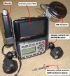
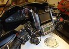
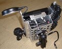
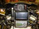
this write up is 10 years old but still very valuable. I have all the parts and am about to start making my own!! thanks for the excellent write up and pictures. So very Helpfull!!!After looking at numerous dash shelf and dash mount designs for the ST, and after attempting a (failed) group buy on the Migsel mount, I decided to forego the expense of an aftermarket bracket or mount and fabricate one from materials that I had on hand and a couple of ram balls purchased online. Of all of the designs I discovered on various motorcycle and GPS forums, the simplest and most uncomplicated design that I found was one first suggested by our own Throttlejockey (linky). I experimented with Fred?s design to develop a bracket that met with my expectations for the aftermarket mount, and made it for a fraction of the cost of retail and none of the hassle or wait. Being a person of very modest (at best) mechanical skills, I believe that this is a simple mod that just about anyone can fabricate. Once you have the parts on hand, this is a 2-2.5 hour task.
Parts list:
? 1 ? piece of flat aluminum 1" wide x 1/8? thick x 8 1/5? long*
? 2 - 1/4" x 20 extruded u-nuts (also called speed nuts -- to reinforce the mount holes that Honda made for the push pins)
? 2 - 1/4" x 20 x 1? stainless mounting screws (stainless in order to avoid problems with rust)
? 1 - tube or packet of blue or red thread lock
? 2 - 3/8? tapered black rubber grommets**
? X - 1/4? x 20 x 1/2? stainless steel screws (these will be used to bolt each ram ball to the bracket)
? X - Ram ball(s) part # RAM-B-348U***
? Basic black automotive spray paint (this will be used to paint the bracket?or you can polish and mount it)
*The 1? wide aluminum is optimal. I made brackets from 3/4" ? 1? ? and 1.5? pieces just to eyeball the difference between them. The 3/4" was too narrow. The support holes were too close to the sides of the bracket and weakened the piece. The 1.5? just looked too wide and bulky. The 1? wide is ideal (IMO).

**The tapered grommet that I used (a $0.40 item at the hardware store - see pic) was a perfect fit for the push pin depressions on the dash?but any 3/8? rubber grommet, spacer, or washer should do (though with washers you may need to use several to get the clearance desired between the bracket and the dash). I chose not to use a hard plastic or metal spacer to avoid any friction damage to the dash in the event that I ever want to remove the dash mount bracket.


***For the ram balls I chose the RAM-B-348U which has a female 1/4? x 20 thread and the standard 1? diameter rubber ball. By using the RAM-B-348U I avoided having to thread the hole in the bracket. I used steel screws (with black caps) and red thread lock to make a permanent mount for each ball. Ram balls are available from numerous vendors, such as The Mount Depot (linky), GPS City (linky), The Mount Guys (linky), or Ram Mounts (linky).
Tool list:
? Drill & bit set
? Screw drivers
? Torque wrench
? Hammer & vice
? Measuring tape
? Pencil or marker
? Metric socket set
? Hack saw & Dremel to cut, shape and polish the bracket
? Punch (to remove the pop rivets and mark your holes for drilling)
Before you begin, grab some towels or shop cloths and cover your tank, front fender, and stuff the open space around the forks. That way should you drop anything you won?t have to worry about scratches, nicks, or loosing something in the ST?s dark abyss. You may want to use some blue painter?s masking tape and cover any other exposed paint to avoid scratching or nicking it, should something be dropped.
Determine how many devices you want to mount (I chose 3 in order to mount a GPS, a satellite radio, and an iPod). This will help determine the length of the metal that you will want to cut. The 8.5? piece is ideal to fit the convex portion of the ST1300 dash. Accurately measure the width of each device and space the measurements for your ram ball holes accordingly prior to marking them.
Once you have cut the aluminum to the desired length, shape it to the contour of the dash using a hammer and a vice, a large piece of pipe or tubing, or shaping it by hand using any hard, round surface you may have available. The aluminum is very malleable and can be shaped without great difficulty. Take your time to get it shaped exactly to the curvature of the dash, checking frequently until it lays flat and centered.


You can leave the corners squared or (as I did) take something as common as a quarter and trace rounded edged, grind them down, and call it done.

I made a pattern of the dash mount holes and bracket using masking tape in order to get the 2 mounting screw holes lined up right the first time. By laying the marked masking tape pattern on your bracket, it is a simple task to get the holes aligned. On the ST1300 dash the 2 OEM mounting holes are 158mm or 6 3/16? (center to center) apart. In the picture below you can see how easy it is to space the mounting holes properly using the masking tape.
Mark the holes for your 2 mounting screws. Keep in mind the builder?s rule ? measure twice, cut/drill once. And here is where your paper pattern for the dash mount will be very helpful. Be sure to use the corresponding diameter bit for your 2 mounting screws so as to eliminate wiggle or wobble in the bracket once mounted.

Test your alignment...

Now mark the holes for your ram ball(s). Be sure that you are using the drill bit corresponding to the diameter of the bolt or ram ball shaft that you choose. In Fred?s design he threaded the bracket and used the M10x1.25 ram ball, screwing it directly to the bracket itself. Since I didn?t want to purchase an M10x1.25 tap, I bought the RAM-B-348U ram ball, securing it from underneath the bracket with a stainless steel screw inside a screw cap. In addition, the RAM-B-348U calls for screws that are the same diameter as the mounting bolts that I selected?1/4" x 20.

Now you are ready to drill. Use a punch and tap a starting point for the bit, and take your time (the drill bit can easily 'wander' in soft material like aluminum).

Drill the mounting bolts first, testing them to insure proper alignment...


Then drill your ram ball mounting holes...
If you plan to paint the bracket, now is a good time. While you perform the balance of the installation, having verified the alignment of the 2 mounting holes and tested your ram ball holes, the paint will have the opportunity to dry.
TIP: After painting the first side of the bracket, I placed it in a pre-heated (about 250 degrees and then turned off) oven with the door slightly ajar. In about ten minutes the paint will bake on and permitting you to paint the other side and carry out a faster reassembly.
Remove the windscreen. Begin by removing the four Phillips screws that hold the windscreen arm cover plates over the mounting hardware of the windscreen. Then remove the four 8mm screws that hold the windscreen onto the mounting rails (take care not to let the windscreen fall off of the rails). Put the windscreen somewhere out of harm?s way.
Next remove the eight push pins that hold the plastic upper dash to the fairing. The top two push pins will not be re-used, but hang on to them as replacement parts.

Then remove the four Phillips screws on the front side of the dash to release the plastic upper dash.

NOTE: You do not have to remove the windscreen rails or the dash?gently slide it down about 1.5? in order to slip on the u-nuts (see pic).


Then button the dash back up. Do not replace the windscreen just yet as it is easier to verify the alignment of the u-nuts and screw the mounting bracket into place without it.
IN HINDSIGHT: After buttoning up the dash I decided that I wanted to run my power cords under the dash and out the small vents at the top edge of the upper plastic dash piece. So I went back in, removed the rails to access the area below, and ran the cables. If you plan to run cables under the dash, it may be easier to remove the four nuts on the windscreen rails and lift off the windscreen still attached.
Now is a good time to clean those hard-to-reach areas around the dash, clean and lubricate the windscreen elevator tracks, and polish up that windscreen?
Once the paint has dried you?re ready to mount the ram ball(s). Depending upon how permanently you want them mounted in the bracket use the corresponding thread lock and screw the ram ball(s) firmly into place.
Now decide whether you want to put the black plastic caps onto the ram ball mounting screws (again, this gives the installation more of an OEM look, protects the dash from the screw heads, and povides just a touch more stability as the bracket sits on the dash). You may also use screw caps for the bracket mounting bolts or simply paint the exposed heads (which is the route I ended up taking).


Don?t forget to place the grommets in place (in the picture you?ll notice that I placed a stainless steel washer on the base of each grommet in order to give them better footing on the plastic ? but I removed these after a test install as they proved unnecessary). Then gently but firmly tighten the 2 mounting screws, keeping in mind that your new dash mount is being bolted to plastic?i.e., do not over-tighten and break something that will be costly to repair or replace.

Once the bracket is bolted down, double-check your work. Make sure that you?ve got adequate clearance underneath the bracket (to prevent chaffing) and that none of the ram ball screws are making contact with the dash. If you've used the plastic screw head caps this is not an issue.


If everything is to your liking, put the windscreen back on?being careful not to over-tighten (standard torque value of the 8mm flange bolts securing the windscreen is 9 ft-lb), install your device(s), and you?re done?provided that you?ve got power run to them, which is another article altogether!


And then, as George would say, ?Get out and ride!?
:
Any chance you still have any of your RBIS dash mounts laying around?
Andrew Shadow
Site Supporter
Hope springs eternal but he hasn't been on this forum for 7 years and it has been even longer since he closed that business so don't hold your breath.Any chance you still have any of your RBIS dash mounts laying around?
This is kinda cool….Hope springs eternal but he hasn't been on this forum for 7 years and it has been even longer since he closed that business so don't hold your breath.
Mount
I got a 1/4" bar to do this project but it's too thick to bend easily? Seems like 1/8 will be easier to work with? Or, how do I efficiently bend the 1/4 bar?Re: ST1300 GPS / Radio / Radar Dash Mount
with the spacers under the bar you will get a lot of movement out of the unit which will eventually lead to failure. The thinner aluminum also flexes and will fatigue eventually.
This is why we removed the spacers and upgraded to thicker aluminum. The attaching point is not curved like the bar either and by clamping the bar in place with the angle you are stressing one side of the plastic mounting point under the dash. This is why our RBIS have been modified to correctly match the mounting point under it.
Finally, the aluminum reflects too much on the windscreen so it must be painted black.
At the very least, get rid of the spacers.
Pretty sure I made mine out of 1/8" aluminum, and it's held up great for over a year. Well except for my lack of prepping it well before painting it 
Has a USB Charger/voltmeter on the left end, a chinesium TPMS on the right end, and my Garmin in the middle. Would share a pic, but I'm a thousand miles from the ST at the moment
Has a USB Charger/voltmeter on the left end, a chinesium TPMS on the right end, and my Garmin in the middle. Would share a pic, but I'm a thousand miles from the ST at the moment
Andrew Shadow
Site Supporter
Assuming that it is a 1/4" thick aluminum bar you most likely aren't going to bend it without cracking it. 1/8" is plenty thick to do that job.I got a 1/4" bar to do this project but it's too thick to bend easily? Seems like 1/8 will be easier to work with? Or, how do I efficiently bend the 1/4 bar?
There are different types of aluminum. I don't know the technical name for it but there is a type that is made to be more easily bent. It is commonly referred to as bendable aluminum. Around here it can be found in some of the hardware stores where they sell the steel square tube, flat bar, threaded rod, etc.. It comes in a 3 or 4 foot length and is a few inches wide. It would work well for this project.
Wow - that's a lot. I'm just looking to mount a small tablet - I actually have the Ram ball mount at the steering stem - but it doesn't position the tablet well so was looking for a dash option.
You may be able to see that I used 3 ball-mounts to secure that assembly. I made this so I could attach/remove those farkles as a single unit versus as separate items. They remained on the bike 24/7 while at home, but I removed them when staying in a hotel while travelling. About the only dashboard item that was difficult to see while riding was the neutral indicator.I actually have the Ram ball mount at the steering stem - but ...
The creativity and ability of the members of this forum never cease to amaze me, incredible.
Share:


