I was trying to troubleshoot some electrical issues with my 2005 ST. I maybe confusing myself because I am looking at a 2003 service manual, but I didn't think there was much difference between these models. My question: Is there a difference between the MAIN STOP relay and the ENGINE SHUTOFF relay? A diagram of the relays under the left side cover indicates they are both in proximity to each other, but I can't identify the Main Stop relay based on wire colors. Also the testing procedures indicate that the main stop relay circuit is not in continuity when voltage is applied where the engine stop relay is in continuity. When I tested what I thought could the be Main Stop relay it tested open without voltage and closed when voltage applied, just like all the other relays I tested. Are there different relays then when ordering replacements? Thanks1

You are using an out of date browser. It may not display this or other websites correctly.
You should upgrade or use an alternative browser.
You should upgrade or use an alternative browser.
Relay question
- Thread starter t-town ST
- Start date
I looked on two enlarged wiring diagrams that I have, (an 06 and 07) and could only find the Main Stop relay. Nowhere on those two diagrams did I see an Engine Stop relay. However, relays come in essentially two flavors - a 4 wire and a 5 wire style. A relay is nothing more than an electrically operated switch - apply current and an electromagnet closes the contacts (the magnet is your hand operating the switch). This is the standard 4 wire relay. A 5 wire relay has an additional set of contacts that will open when the magnet is energized. Of course, there are many other relays with more sets of contacts but for our bikes and most cars, the standard 4 and 5 wire ones are used.
My HSM shows only an Engine Stop Relay in the pictorial, so I have to assume there is only one relay - whatever it is called. It is located outboard (closest to the fairing), just aft of the Fuse box B. No doubt someone will post a picture for you.
My HSM shows only an Engine Stop Relay in the pictorial, so I have to assume there is only one relay - whatever it is called. It is located outboard (closest to the fairing), just aft of the Fuse box B. No doubt someone will post a picture for you.
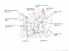
Here is the pic I thought someone else would post more quickly than I. I sort of blew it when I shot the photo, but you can see from the top pic (which is similar to the lower one) the location of the engine stop relay. I saw no mention of two relays that kill the engine.I was trying to troubleshoot some electrical issues with my 2005 ST.
In the lower pic (After 03), the word ENGINE points to the Engine Stop Relay.

jfheath
John Heath
I think that the term Engine Stop Relay may be an error. The copy that I produced (and which is also copied in this thread) came from a Honda Service Manual for 2004.
Yet the circuit diagram in the same manual does not show an 'Engine Stop Relay'. It shows a 'Main Stop Relay'
The Honda circuit diagram shows a Red/Black and Green going to the coil - the trigger wires of the 'Main Stop Relay'. The Red/Black comes from Ignition switch - which gets its power from the 30A fuse that is on the starter solenoid. This same lead also provides power for fuses A & D on the non-ABS version, and (fuses A,B & E on the ABS version).
So the 'Main Stop Relay' is triggered when the ignition switch is turned on.
The other two leads are for the switched power - White and White/Green. The White lead gets its power from Fuse B or Fuse C (ABS version). This is the fuse that supplies power for brake lights, horn, passing switch and one of the quartet harness accessory feeds. Following the circuit diagram, these are the only components that are supplied from the White/Green Wire.
So the Main Stop Relay only turns on the circuit for the brake lights and horn plus the passing switch (UK) and an accessory feed. Why 'Main Stop', I don't know. 'Stop Light Relay' would make more sense. I think that 'Main Stop Relay' may be a misnomer. It is possible that someone has confused the term 'Engine Stop Switch' with 'Main Stop Relay'. The Engine Stop Switch is not directly connected to any relay for devices that it feeds.
Unless anyone else has any other ideas ?
Regarding the replacement relays. Most of the relays in the main cluster are interchangeable. But beware buying a third party relay which may have circuit protection in the form of a diode across coil, it matters which terminal is connected to +12v and which is terminal is connected to earth. I looked on the back of my relays - there was no consistency between which terminal had the +ve wire and which had the negative. (So during the build, the engineers just take the two leads and push them onto the trigger blades, paying no attention to which is which. (Which is OK if there is no diode, it doesn't matter). So make sure you buy relays that do not have the built in diode protection - or make sure that your relay trigger terminals are the correct way round for the diode.
Last edited:

This diagram in in my 2003 service manual, in the ignition section. The ESR is shown at the top right. It looks to be energised by both the bank angle sensor and the engine stop switch/ignition switch circuit.
I think you are reading the schematic improperly. You need to go to an enlarged (like yours) diagram of the wiring and look at the relays. I believe, (going from memory here) the bank angle switch is normally closed and in series with the stop relay. When the bike tips over it opens the path to ground. With no path to ground, the stop relay, in series with the bank angle sensor opens shutting the bike off.
This diagram in in my 2003 service manual, in the ignition section. The ESR is shown at the top right. It looks to be energised by both the bank angle sensor and the engine stop switch/ignition switch circuit.
My point is, you need to look at the whole wiring diagram, including a detail of the relays, and not just a part of it.
Thanks for all the help. I have attached the photos out of my 2003 service manual that talks about both the main stop and engine stop relays and their apparent opposite function ( in terms of relay electrical function) Diagrams seem to be inconsistent in location of engine stop relay . 


jfheath
John Heath
This mixture of diagrams is interesting in how confusion seems to have developed.
Regarding the simplified diagram from the manual that @TerryS has included - I have to admit I don't recall noticing that before - I tend to ignore these as often they do not contain the info that I need, or they contain errors or over simplification. In this diagram for example, there is no power source shown, and it could be assumed that the PGM FI unit is the source of power. In fact the Bl/W lead is powered from the ignition switch, and a multiway connector allows this power to be distributed to many devices, including the ECM / PGM FI unit.
However this simplified diagram does show the wire colours to the device that it labels as the Engine Stop Relay - Bl/P, R/O, Bl, Bl/W. In the main circuit diagram the relay that has this combination of cables is the Bank Angle Sensor Relay, and that does sit between the Bank Angle Sensor and the Stop switch.
So I have a theory.
Engine Stop Relay = Bank Angle Sensor Relay
Main Stop Relay = Relay providing power for brake stop lights, horn, passing switch, accessories.
Any diagram that labels a Bank Angle Sensor Relay AND an Engine Stop Relay is to be treated with caution.
Which relay is which in the line drawing diagram of the relay cluster, I am no longer certain. I know that I checked the Bank Angle Sensor Relay and the Fuel pump Relay, and I have looked at others at different times and have never found anything that contradicts my diagram. But I cannot be certain that I have checked the position of every one if them with the diagram.
Most relays are the same, except maybe for the turn signal relay.
Last edited:
Andrew Shadow
Site Supporter
I think that that must be an error in the text, not the wiring diagram. There should be continuity when 12V is applied.and their apparent opposite function ( in terms of relay electrical function)
The wiring schematic shows a relay that closes the switched power when 12V is applied, not one that opens. This is consistent with how a four-pole electrical relay operates.
Thanks, I think that makes the most sense.I think that that must be an error in the text, not the wiring diagram. There should be continuity when 12V is applied.
The wiring schematic shows a relay that closes the switched power when 12V is applied, not one that opens. This is consistent with how a four-pole electrical relay operates.
Thank you for your time and interest. That does make the most sense.This mixture of diagrams is interesting in how confusion seems to have developed.
Regarding the simplified diagram from the manual that @TerryS has included - I have to admit I don't recall noticing that before - I tend to ignore these as often they do not contain the info that I need, or they contain errors or over simplification. In this diagram for example, there is no power source shown, and it could be assumed that the PGM FI unit is the source of power. In fact the Bl/W lead is powered from the ignition switch, and a multiway connector allows this power to be distributed to many devices, including the ECM / PGM FI unit.
However this simplified diagram does show the wire colours to the device that it labels as the Engine Stop Relay - Bl/P, R/O, Bl, Bl/W. In the main circuit diagram the relay that has this combination of cables is the Bank Angle Sensor Relay, and that does sit between the Bank Angle Sensor and the Stop switch.
So I have a theory.
Engine Stop Relay = Bank Angle Sensor Relay
Main Stop Relay = Relay providing power for brake stop lights, horn, passing switch, accessories.
Any diagram that labels a Bank Angle Sensor Relay AND an Engine Stop Relay is to be treated with caution.
Which relay is which in the line drawing diagram of the relay cluster, I am no longer certain. I know that I checked the Bank Angle Sensor Relay and the Fuel pump Relay, and I have looked at others at different times and have never found anything that contradicts my diagram. But I cannot be certain that I have checked the position of every one if them with the diagram.
Most relays are the same, except maybe for the turn signal relay.
Most relays have constant ground to one coil terminal and the +12v power to the other coil terminal is switched. Some relays have constant power (when the key is on) to one coil terminal and the other coil terminal's connection to ground is what is switched.
This diagram in in my 2003 service manual, in the ignition section. The ESR is shown at the top right. It looks to be energised by both the bank angle sensor and the engine stop switch/ignition switch circuit.
The engine-stop relay is like a starter relay, in that there are one or more switches in line with both coil terminals that must be closed (on) for there to be current through the relay coil. The engine kill switch controls +12v, and the tip-over relay controls ground.
Share: