Now I have something "new" to me... and a new project

I'm going to make some suggestions based on my experience with making living building and racing these things.
1nYD_hN0WP4XgeMBg2wr7__z_uNL2f9Oj


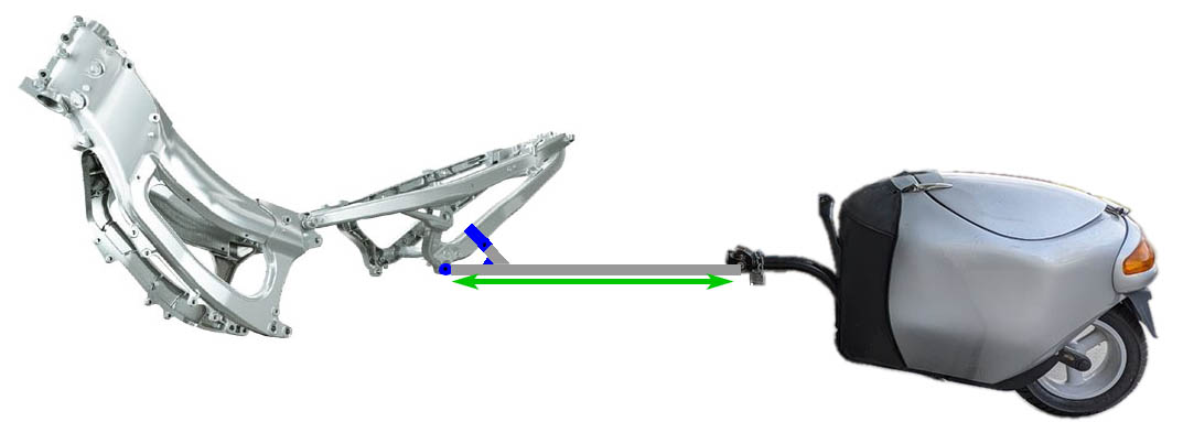
I see potential issue with this design. Due to offset mounting points, forces from pulling trailer and braking will generate lots of torque at attachment point on frame due to long cantilever arm.
1YqyzPGZfZ15AdWU_EchEOkApOnC6qWJe


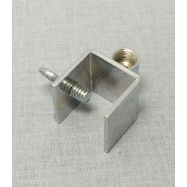
Not to mention your intersection is at odd angles, so you'll need double-square clamp made for that specific angle between 2 beams. Something like these. You can just weld 2 sections of larger square-tubing at proper angle. Slice them in half and add lugs for clamping bolts.
1L0sZd4ehzocqceg_GaB2rIK0XMc-s79v
1xLmPVKKIEI-GUkUHf-BA92iK-biXEstR


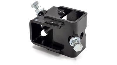
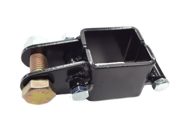
Torque at that junction will add significantly more stress on both your tow-bar and frame than pulling or braking forces. It's like hammering or pulling nails, when forces are in-line with material, it's very strong. But when bending & twisting forces are applied, like bending half-installed nail laterally with pliers, it will break very easily with repeated stress-cycles. Whatever clamping mechanism you use will need to be 4-5x stronger than tubing or frame itself. That torque will also squat and lift your back-end up & down when you accelerate or brake.

That's why tow-bars for ST1300 and Vespas are directly in-line with forces they will face. Least amount of stress on parts for any given load. Also won't push up or down on frame and compress/extend suspension.
1HmN_WxDBW52dSKRCDFWs5hNf-3JNroUz


1A_2H6EPozchYRhKKg1TJPN3-6qqG18IR


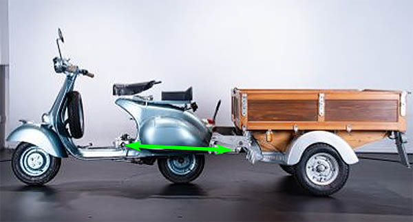
You want it to be like ST1300 or Vespa tow-bar where forces are inline and it only experiences tension & compression. This lowers stresses at attachment points on frame significantly.
1nK5sfHTI9RbVjHo3zMKPIuMbpYralm_x


Can use pre-made eyelets for mounting to lower part of subframe with longer bolt. Upright w/gusset to prevent rotation can just use longer square-clamp. Again, loads will be in-line with material (and triangulated), so very little clamping force needed.
1rhNy9Ew6vu4cIAcO01ezZgqhSUkLBWZU
1h927Nen7vxSX5g3vT5cQVT3wq2bF5the


Make it as straight as possible like ST1300 tow-bar for strongest load-handling. Can get pre-made loops for end. Much, much stronger than angled cuts which focuses significant percentage of loads at points on outer skin.
14fzqLiiSzadT_kRHKH-wsXswIZJc2m8x


Notice on ST1300 tow-bar, there's an upright to deal with rotation, but it's very minor thin bracket because there's very little torque since loads are in-line with beam.
1pObKjF20eq6_rgOuYpYlmdwUJkfDKLBz


A plate on inside radius for mounting trailer-ball. Rather than straight edge, better design is to make it crescent-shaped so some of it will run forward with tubing to re-inforce it and reduce stress riser at interface.

I wouldn't use stainless for this, it's good for looks, but not strength. Better to use 4130 chromoly or 1020/1022 mild-steel. Even though chromoly was designed to build aircraft frames with oxy-acetylene torche, it can be TIG-welded easily. Be sure to do pre-heating and post-weld annealing to make HAZ tougher and less crack-prone.

Of course, it really comes down to strength-to-weight ratio. Z-shaped load-path with offset end-points will end up 2-3x heavier than ST1300 tow-bar for 1/2 the strength. Better to over-build it than under. :)
 
Last edited:
That's pretty detailed, and while I've never built frames or welded anything, it seems to make sense when explained that way.
Many counselors.
 
I'm no metallurgist but I think the second version could actually turn out stronger with the extra gusseting to resist flexing of the new......I spose it's a subframe.
Plus like you say when you're not using the trailer it will fit in better in a cosmetic sort of way. The frame you're drilling through? Is it a subframe itself or the main frame?
I think it's great you're getting good input from folks who know what they're talking about, pity he couldn't take the job on for you.
Good luck.
Upt.

The bike frame I'll be drilling a hole in is the rear sub-frame. Most bikes have one that goes back from the main frame that usually ends just behind the engine... and on most bikes the seat and saddlebags and top cases all sit on that rear sub-frame. Same thing here on this bike. The engine is in the main frame up front and the seat and storage box and rear luggage rack are all sitting on the rear sub-frame. As in every bike the rear sub-frame is designed to handle the weight of 2 riders plus a bit of luggage.
 
The bike frame I'll be drilling a hole in is the rear sub-frame. Most bikes have one that goes back from the main frame that usually ends just behind the engine... and on most bikes the seat and saddlebags and top cases all sit on that rear sub-frame. Same thing here on this bike. The engine is in the main frame up front and the seat and storage box and rear luggage rack are all sitting on the rear sub-frame. As in every bike the rear sub-frame is designed to handle the weight of 2 riders plus a bit of luggage.
Which was my train of thought. I will have to stop thinking......it hurts.
Do you think the original subframe mounts will be adequate as standard.
Upt.
 
Good ideas to think on @DannoXYZ .
But a detail that is missing is that there will be two attachment points on each side. One where you half circled in the picture and another toward the rear of that where the hitch crosses the lower sub-frame just before it exits the bodywork. So it won't be bolted just to the one location at the front end of the hitch but two locations. I am giving more consideration to making the hanger thicker, to 1/4 inch, to take up some of that torque force. I looked at some of the hitches Uni-Go makes and sell for bikes for their trailer. The forces are not exactly the same as for a typical 2 wheeled trailer. Some of their hitches do attach higher in the frame and drop down at the back. Most only have 4 attachment points, 2 on each side, which is what they recommend. I'll be adding the hanger bar as a 5th attachment.

Unfortunately just looking at the frame alone doesn't tell the whole story about where it is possible to connect stuff. The rear shock alone prevents attaching down low without a lot of complicated bending and twisting around to avoid issues with that. And don't forget that I am now not going to be using U-bolts but rather putting a bolt through the bike frame to mount the hitch at those 2 points on each side with a spacer to fill the inner gap.

Attachment points.jpg

@Upt' North , I do. There is a lot of structural support at those mounts. As on the ST then engine on this bike also serves as part of the structure of the frame. The rear engine mount is at the front bottom point of the rear sub-frame.
 
Last edited:
I wanted to say that I have read a lot of comments on the several forums I am on about the hitch being lower and inline with the direction of pull. That is very important, critical even, for a typical 2 wheeled trailer. On those the trailer tongue is best kept level with the ground or up/down forces are transferred to the bike with very negative results. But a mono-wheeled trailer has very different dynamics than a 2 wheeled trailer I have learned (I am always doing research on stuff). A mono-wheeled trailer must HANG under the hitch receiver to assist in keeping it vertical. Not just the design of the receiver using a universal joint. The heaviest load should be kept at or below the line from the receiver to the axle for best performance. That is why the Uni-Go tongue is designed to be so high compared with typical trailers that have 2 wheels. And that is why the receiver is set so high. The pulling force is not just inline with the ground (forward) but also upward to some degree.

I do want to say thank you for all the comments to date. I do take note of them and consider how I can improve the design I am making. I don't discount any opinions. A lot of you as well as a lot of members of those other forums have experience in metal work and even vehicle framing and all comments are helpful.

Thanks.
 
Good ideas to think on @DannoXYZ .
But a detail that is missing is that there will be two attachment points on each side. One where you half circled in the picture and another toward the rear of that where the hitch crosses the lower sub-frame just before it exits the bodywork. So it won't be bolted just to the one location at the front end of the hitch but two locations. I am giving more consideration to making the hanger thicker, to 1/4 inch, to take up some of that torque force. I looked at some of the hitches Uni-Go makes and sell for bikes for their trailer. The forces are not exactly the same as for a typical 2 wheeled trailer. Some of their hitches do attach higher in the frame and drop down at the back. Most only have 4 attachment points, 2 on each side, which is what they recommend. I'll be adding the hanger bar as a 5th attachment.

Unfortunately just looking at the frame alone doesn't tell the whole story about where it is possible to connect stuff. The rear shock alone prevents attaching down low without a lot of complicated bending and twisting around to avoid issues with that. And don't forget that I am now not going to be using U-bolts but rather putting a bolt through the bike frame to mount the hitch at those 2 points on each side with a spacer to fill the inner gap.

View attachment 328213
Through-bolt will be good attachment. Be sure to have spacers with large contact surface area. Make sure spacers you use are large diameter with lots of contact surface area on both sides. Looks like they should have angled faces to have full contact on both sides. This will prevent twisting/bending tubing when clamping bolts are tightened. Idea is you want zero gaps between beam and frame before tightening bolts for zero residual stress on tubing. Maybe start with something like this angled washer and mill/grind to fit.

1R7n9FExTlJVklpVmhuY3YT4B-hq47IHn


Upright/hanger faces zero torque. All its loads are in tension/compression, so 1/8 is fine. Highest torque is at attachment points of beam. So might want to go 3/16 wall-thickness there and taper to 1/16 at end/tips (butted tubing).

Torque is tricky to figure out, almost countre-intuitive. It’s highest at pivot/clamp point. Lots of people think that fork tubes face highest stress at tips where wheel attaches. It’s actually at opposite end where tubes are clamped to lower triple-T. Easily 5-6x more torque there than at tips and also where pretty much all fork tubes bend or break in crashes.

Project’s coming along nicely! Can’t wait to see how it turns out. I was originally considering trailer to take my little dog on rides. But she’ll fit into top-box just fine. :)
 
Last edited:
Also wanted to add that my welder friend who came to my house and spoke with me was thinking that using M8 (8mm or 5/16") bolts is more than really needed to bolt the hitch to the frame but that's when he reiterated, again, that he likes a bit of overkill so that would be what he would do. He was initially thinking M6 (6mm or 1/4") bolts. He said definitely grade 8 but he was thinking in terms of SAE sizes and grades. I found out that the metric equivalent to SAE grade 8 is Metric grade 10.9.
 
Through-bolt will be good attachment. Be sure to have spacers with large contact surface area.

Upright/hanger faces zero torque. All its loads are in tension/compression, so 1/8 is fine. Highest torque is at attachment points, so might want to go 3/16 there and taper to 1/16 at end/tips (butted tubing). Make sure spacers you use are large with lots of contact surface area on both sides. Looks like they should have angled faces to have full contact on both sides. This will prevent twisting/bending tubing when clamping bolts are tightened.

My thoughts exactly. (my emphasis added in quote)
 
BTW- If you look closely at some of the photos showing the square tubing coming out the back of the bike you will note that they are really not much of an angle off of horizontal. Only 4 deg from horizontal which is less than I've seen on many standard hitches. The view of those tubes inside the body of the bike look like they are angled down and back a lot but that is an illusion of the camera angle. The drop on the design I am making is really no different than the drop on a standard receiver hitch where the receiver tube is almost vertical under the mud flap of any bike that has that type. The drop on what I am making is about 10 inches from the horizontal section of tubing down to the center of the Uni-Go receiver... so not all that much.
 
Torque is generated between contact points. So draw straight line between where loads start (hitch-ball) to attachment point on frame. As long as line is in-line with forces it faces, it will have zero torque. Anything outside of this line will face a bending torque.

So there’s 2 areas of high-torque here. One is attachment to frame. Other is where drop hanger connects to beam. Gusset plate will deal with torque there as it’s not as high as torque where it’s bolted to frame.
 
Torque, welds, contact surface area, metric to SAE conversions, geometry, angle of incidence, extension and compression, tongue weight, butted tubing, air- fuel ratios and stoichometric volume... my eyes are glazing over.

Maybe I should just stick with the string idea? But then we start having to consider "string" theory!!!
:rofl1:
 
Maybe I should just stick with the string idea? But then we start having to consider "string" theory!!!
:rofl1:
I shouldn't further stray from the topic, but as we're now into metallurgy and engineering and quantum physics...
How long IS a piece of string, anyway?
For reals.
 
I shouldn't further stray from the topic, but as we're now into metallurgy and engineering and quantum physics...
How long IS a piece of string, anyway?
For reals.
Infinitely long and infinitely short!!! :p:rofl1:
 
Top Bottom