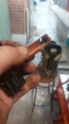
There are a couple of bus connectors like this. They are shown in later circuit diagrams for the ABS models.

This was taken from a post from
@SpikingJC - link here
https://www.st-owners.com/forums/th...atics-for-03-07-standard.124038/#post-2013259
You need the 03-07 Deluxe version - ie ABS - in post #3 .
The two connectors shown in the diagram are labelled as 14P (Y). and 20P (P). which represent the number of pins and the colour.
But in the diagram, the Yellow connector is shown connecting Black/white leads which are used for powering relays and many important ignition components - ie not earth. The Pink connector is shown connecting the mainly green earth wires and there are three separate buses in the same case according to the diagram.
I cannot make this diagram match with what people say (consistently) about the yellow earth connector so I suspect something is labelled incorrectly. But the colour of the wires going into them is your best clue. The point is that there are similar connectors for both +ve leads and -ve leads. Make sure you know which one does what.
I've never had to delve into this part of the wiring. I have often wondered whether the overheating fault is due to people adding electrical accessories and relying on existing wiring to carry the current. I have a completely separate home made harness, fused and relayed, attached to the battery +ve and -ve posts so that it is completely independent - apart from the relay coil trigger which come from the quartet harness.
My UK workshop manual which is for the 2004 models and was the latest available when I bought my 2006 model in early 2007, does not show these connectors. But my manual is clearly out of date for the 2006 model. Still useful, but I have to double check everything. I don't know the source of
@SpikingJC 's diagrams.


