Recently, someone here mentioned that Honda spec'd some pretty soft metal when they designed the threaded throttle-body shaft. Speaking from the voice of experience, I tend to agree

:. Another aspect going against us, is that the shaft has two flats on it, meaning there is about 40% less thread on it's circumference for the nut to engage. This makes it that much easier to strip the shaft when the nut bottoms-out (and torque goes up). It just "feels" like it should tighten a little more, then you find out the hard way it was tight enough.
Undoubtedly, Honda uses these flats to secure the throttle-body's "butterfly" valves to the shaft. For those installing the CC throttle arm for the first time (and depending on how many threads remain on yours, dparker182), you can use these flats to your advantage. I bought an extra 7mm nut, a thin "internal" star washer, and a short #6 x 32 set screw. First, place the star washer on the shaft, then the CC throttle arm, and finally thread the new nut on the shaft. Carefully, repeat, carefully, tighten the nut far enough (but not too far) for everything to cinch together, such that one of the six flats on the nut are parallel to the flat on the shaft. Mark the flat on the nut. Remove the nut, then drill and tap a #6 x 32 hole through the nut at the flat you marked. Re-install the nut onto the shaft using generous amounts of blue Loctite 242 on the "main" threads, tightening the nut to the same location where the flat (now with the tapped hole) again aligns with the flat on the shaft. Using more Loctite, install and tighten the set screw onto the throttle-body shaft. The set screw mechanically "locks" the nut to the shaft to inhibit loosening. Done.
Hope that helps (it did for me).
Matt
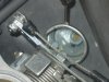
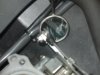
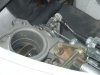
p.s. 6/1/08 edit.. added two out-of-focus pics. If you look closely, you can almost make out the nut w/ the set screw going through it. My throttle arm is made from an aluminum rc airplane servo linkage which, because of its thickness, required some filing to create some "dog leg" reliefs around the throttle drum to gain more engagement onto the throttle-body shaft (i.e. so the nut can thread on as much/far as possible).
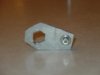
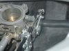
p.p.s. 7/19/08 edit.. the fix using a set screw to secure the nut to the throttle-body shaft worked really we'll, but it revealed another weakness (read on). I was messin' with the CC dip switches and set them to a very aggressive (low-HP to high-weight) setting. Because the speed limit is something like 30 mph around my neighborhood, I had the bike in 3rd gear (very responsive part of the torque curve), so when I pushed Set, the bike just about threw me off the back (good thing I was holding on tight!). Back at the house, I noticed the CC cable now had some slack that wasn't there before. The slack was due to the CC throttle arm being yanked hard enough to cause the arm to rotate on the throttle-body shaft. Knowing I couldn't tighten the nut any further (it was locked to the shaft w/ the set screw and Loctite), I needed a way to keep the arm from rotating - ever. In the 3rd, 4th, and 5th photos below, you can see a small aluminum brace I made that essentially locks the throttle arm to the nut. It simply fits over the nut, and is bolted to the arm with a #6-32 socket-head screw and nylock nut. The last photo is intended to show the brace doesn't impede travel even at WOT (Wide Open Throttle). I have been using the CC for several weeks now, and the fix appears to have worked well. And yes, I did remember to change the CC dip switches back to a high-HP to low-weight setting so it doesn't pull too aggressively. In other words, if using this setting, your CC probably won't exert the kind of force mine did. I'm just happy I exposed the weakness (and found a fix) prior to putting everything back together.